Verify the type of monitor firmware on your Dragon12-Plus2 board:
-
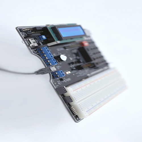
Apply power to your Dragon12-Plus2 Rev D
board via a USB cable connecting to a USB port.
-
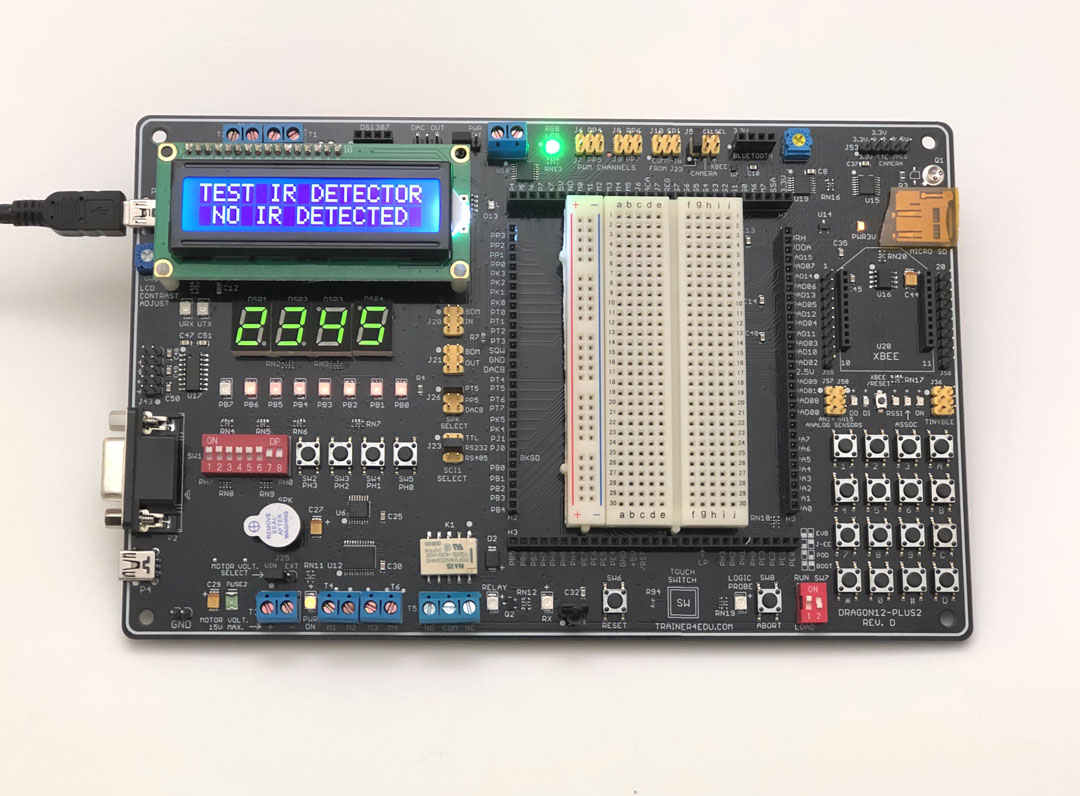
Observe the 8 port B LED indicators.
-
If your board is pre-installed
with D-Bug12 monitor firmware, the 8 port B LED indicators will flash
sequentially from
left to right and the speaker will chirp once when the
board is powered up.
-
If
you ordered the board with serial monitor firmware for the CodeWarrior, it would be
pre-installed with the serial monitor and a factory test program. The state of the left switch of the 2-position DIP switch (SW7) is
tested by the serial monitor for selecting RUN or LOAD mode during power up or
reset, and the 8 port B LED indicators will flash sequentially from right to left and the speaker will chirp once to indicate that the serial monitor
firmware
is functioning. The right DIP switch is not used by the serial monitor.
For more information please see this video:
http://www.youtube.com/watch?v=gmwBMWII0p8&feature=related
If the left switch is placed in the "LOAD"
mode (in the "low" position) the monitor will wait for a command from
the host PC.
If the left switch is placed in
the "RUN" mode (in the "up" position) the 8 port B LED indicators will
flash again from left to right to indicate that the program execution is diverted
to the user code.
The
CodeWarrior communicates with serial
monitor firmware only in LOAD mode and so in order to interface with the CodeWarrior you have to
place the left switch
in the �low � position. The 8 port B
LED indicators will flash from right to left and
the speaker will chirp once
when the board is
powered up.
If
your board does not communicate with CodeWarrior, the first thing
you should check is that if the left DIP switch of the SW7 is in the
LOAD mode ( in the "low" position).
-
If monitor firmware is not
installed or is erased
by a BDM,
the 8 port B LED indicators will not flash sequentially during power up or reset.
The
DRAGON12-Plus2 board comes with a
built-in USB interface based on the FT231XS. The driver for the FT231XS must be
installed properly before using the board.
Install and verify USB driver:
-
Plug the Dragon12-Plus2 Rev. D board to your PC via
a supplied USB cable. Let Win10 search the
driver on the web and automatically install it for
you. If the auto installation does not work
for your PC (it's very unlikely), you can download
the exe file and then run it to install the driver
manually.
https://www.ftdichip.com/Drivers/VCP.htm
the version is 2.12.18
or you can download the
setup executable,
unzip it and then click on the EXE file.
-
Verify it in
Device Manager
-
Once you
have verified that the USB driver is properly
installed, you may invoke the IDE (CodeWarrior or
AsmIDE).
-
If you
are going to use CodeWarrior IDE and have not
installed it you need to
Download and
configure CodeWarrior http://www.trainer4edu.com/dragon12/codewarrior_hcs12.html
For AsmIDE users:
The software tool AsmIDE including the assembler
(AS12.exe) is used with Freescale D-Bug12 monitor. All sample programs are tested
under the D-Bug12 monitor. If you plan to use the CodeWarrior
IDE with Freescale serial monitor, or you have been using the MiniIDE, you can ignore the AsmIDE and AS12.exe, but all sample programs can
run under the MiniIDE or can be converted to run under
the CodeWarrior.
If the
AsmIDE does not communicate with your Dragon12-Plus2 board then you need to check if
the COM port number that is assigned by the AsmIDE matches the
USB-to-Serial COM port number that is
assigned by Windows' Device Manager. The Device Manager assigns the
USB-to-Serial COM port number randomly and it does not know which COM port
number that AsmIDE is going to use.
In order to find the USB-to-Serial COM port number
that is assigned by Device Manager, you can click through
"Control Panel -> Systems -> Hardware -> Device Manager -> Ports".
The
USB-to-Serial COM port number will appear.
For setting the COM port of the AsmIDE to match that USB-to-Serial COM port
number, you can click through "View-> Option->Terminal Window Options" menu,
then select the correct COM port from COM1 to COM4.
In order to establish a reliable USB
communication, always connect the DRAGON12-Plus2 Rev. D board to your PC's USB port first
before invoking the AsmIDE, otherwise the AsmIDE will not be able to
communicate with the DRAGON12-Plus2 Rev. D board. During a debugging session, if you
accidentally unplug the USB cable from the DRAGON12-Plus2 Rev. D board, you need to re-establish the
USB communication. The AsmIDE will not recognize the DRAGON12-Plus2 Rev. D board again
if you just simply re-plug in the USB cable.
To
re-establish the USB communication you
need to exit AsmIDE and power cycle the
DRAGON12_Plus2 Rev. D board (disconnect the USB cable from the DRAGON12-Plus2
Rev. D board, then re-plug in the USB cable),
then you can invoke AsmIDE again and the AsmIDE will start to
communicate with the DRAGON12-Plus2
Rev. D
board. If this does not work, you
may need to restart
your PC.
If
restarting the PC does not solve the problem, you can try it on another PC.
Download the MC9S12DG256 Device User Guide
http://pdf.datasheetcatalog.com/datasheet/motorola/9S12DT256DGV3.pdf
Download the D-Bug12 Reference
Guide, DB12RG4.pdf
http://www.ece.utep.edu/courses/web3376/Interrupts_files/DB12RG4.pdf
Download the AN2548.pdf
(serial monitor)
http://www.freescale.com/files/microcontrollers/doc/app_note/AN2548.pdf
Download the AN2153.pdf
(serial bootloader)
http://www.freescale.com/files/microcontrollers/doc/app_note/AN2153.pdf