| |
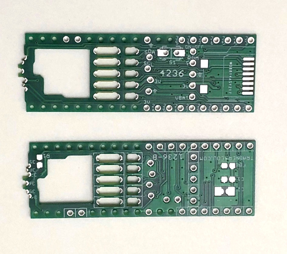
FRDM4236 features:
1.
Staggered castellation for 1mm pitch holes, the
staggered
castellation holes are a bit larger and easier to be
soldered without creating a solder bridge to an adjacent
hole/pad.
2.
Built-in SD card. When SD is not used, the D34-D39
can be used as I/O pins.
3.
All components can be 0805, except C2 can even be 1206,
easier for DIY.
4.
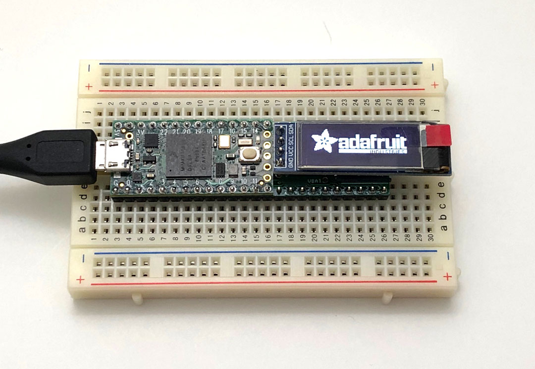
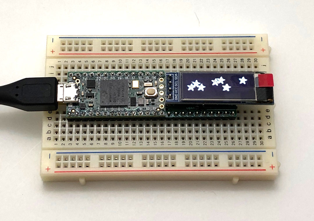
Self-locking pads for a 128x32 OLED display.
5.
Teensy 3.6 footprint and breadboard friendly.
6.
Low cost, PCB and all parts including two 24x1 male
headers should be < $5.
Soldering instructions:
Because this breakout board has 1mm pitch castellated
holes, you need to prevent no-clean flux residue trapped
around the 1mm pitch holes, especially the final product
is made of 2 stacking boards. So if you use non-clean
flux, use as little as possible.
After soldering, flux residue could be conductive
especially if board is contaminated.
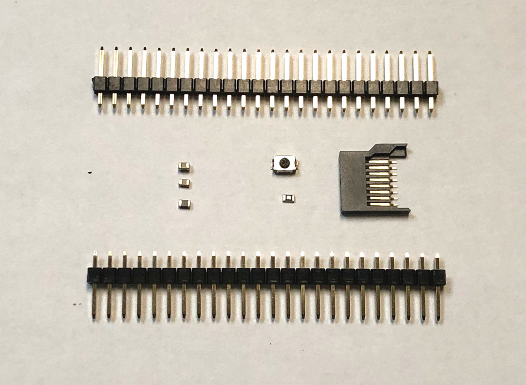 |
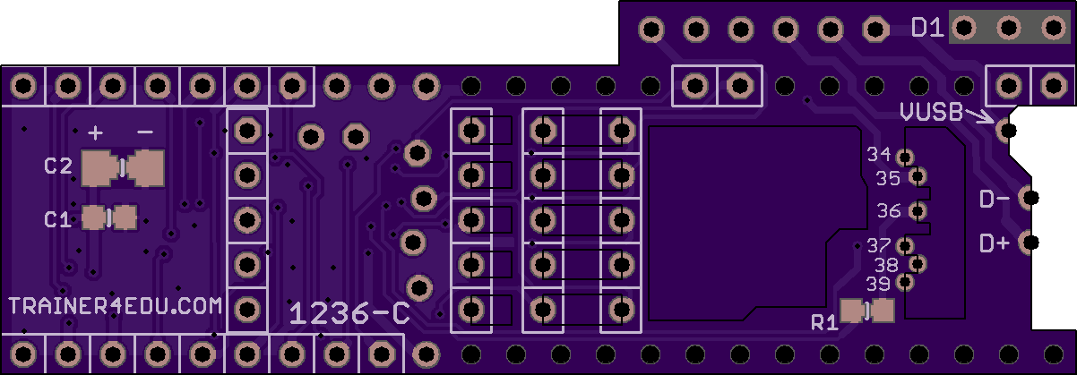
1. These are the parts you need:
-
FB1:
120-150 ohm Ferrite Bead, 0402-0805 (This
part is omitted on the new board)
-
C1: 0.1UF,
0402-0805
-
C2: 10-47UF,
0402-1206
-
R1: 22 ohm,
0402-0805
-
S1:
Pushbutton Switch
-
J1: 24x1
male header, 0.1" pitch
-
J2: 24x1
male header, 0.1" pitch
-
SD1: Micro SD card
slot
|
 |
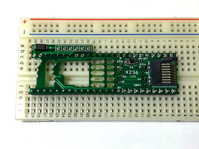
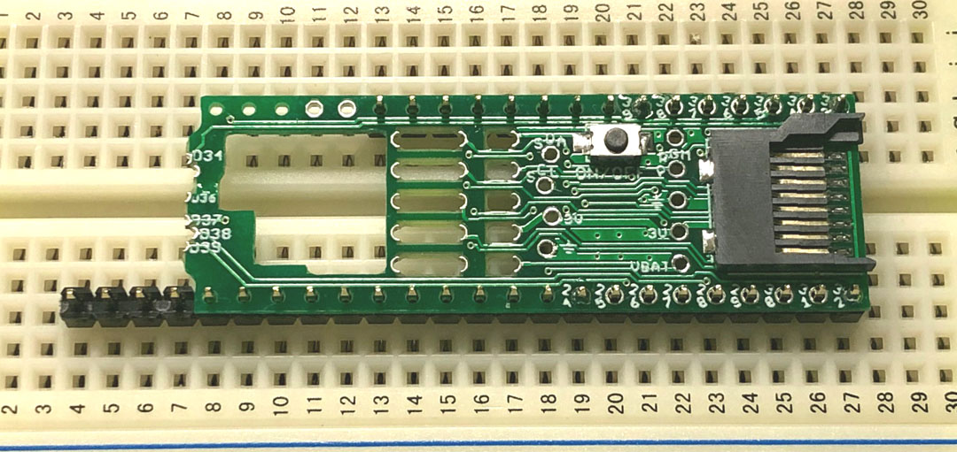
2. Solder all components, FB1, C1, C2, R1, S1,
SD1, on the breakout board. After soldering, If
you use water soluble flux, you can wash it with
soap, brush it with a tooth brush, rinse it
thoroughly and dry it using a heat gun or a hair
dryer. |
 |
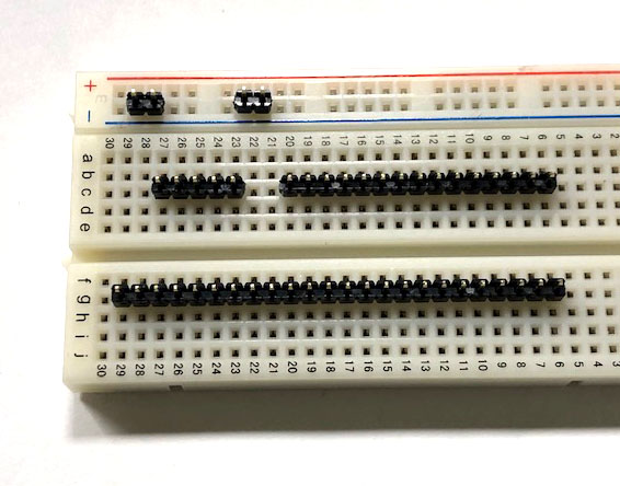
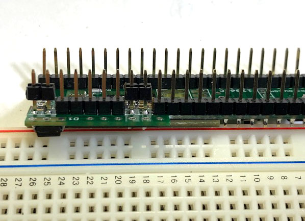
3. Break J2 into 3 pieces, 7x1, 2x1 and
15x1. Place J1 and 15x1 headers on a
breadboard as shown at left. Make sure that the
headers are 0.6" apart. Do not need 2x1 and
7x1 headers for the time being.
Place the FRDM4236 over the male headers,
right-aligned. It will leave the 4 left-most
pins of J1 uncovered. This is
important. If you misalign it, it will
be difficult to undo after soldering.
|
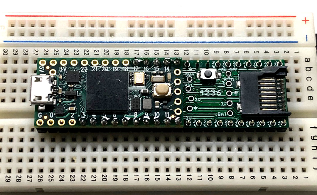 |
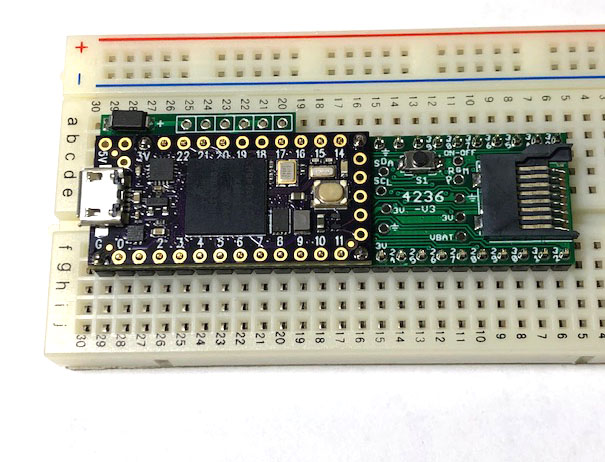
4. Place your Teensy 4 over the breakout board,
left-aligned to the GND pin at low left conner.
Start soldering 4 pins in this order: D3, D13,
D12, D17. Solder pins while pressing down two
boards. |
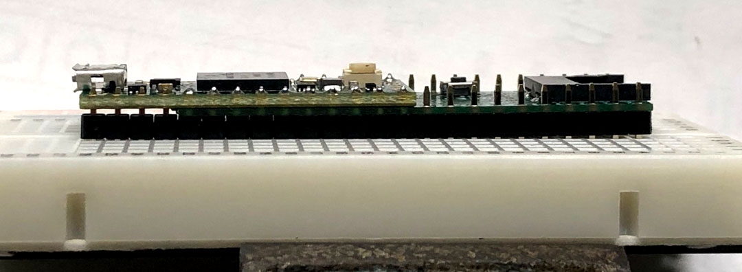 |
5.
Once those 4 pins are soldered, check to make
sure there is no gap between 2 boards. If there
is, you still have a chance to correct.
Then solder D4-D11, D14-D16 pins, install
7x1 header left-aligned, and solder all 7 pins,
finally solder all other remaining pins.
After that, you only have an opening for a 2x1
header on D18 and D19.
|
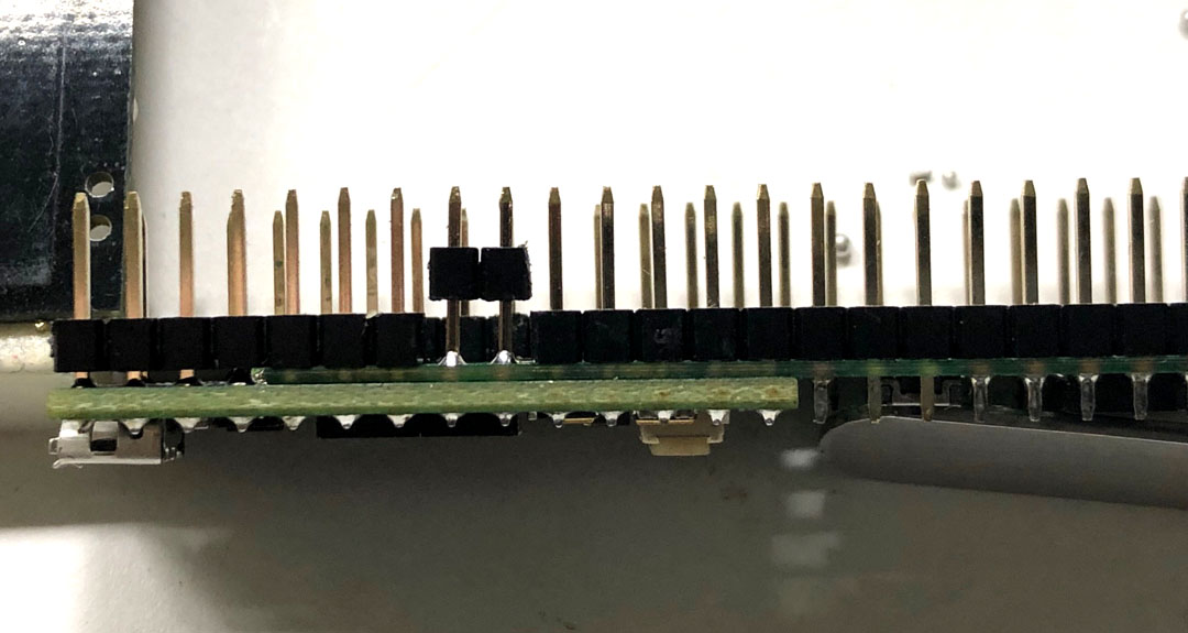 |
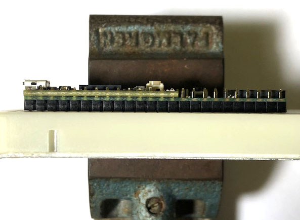
6. Try to fit the 2x1 header into the opening,
you may need to use a small file to make it
narrower, then turn the 2x1 header upside down
and solder the pins to both PCBs. It's easier to place the board on a
breadboard and solder the pins on Teensy 4.0
first, If you heat the pin a little longer, the
solder may flow down to FRDM4236 board. If 2x1
headers are not turned upside down, the plastic
rail of the header may block solder flow, or
solder may not flow down well. The connection
may not be reliable.
Finally push the plastic rail
down. |
 |
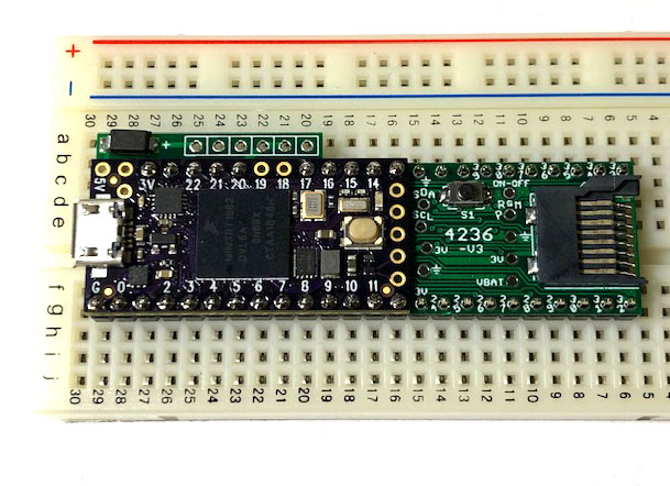
7. It's not difficult to solder all castellated
holes. The 1mm pitch holes need to be soldered
with a small solder iron tip. Keep pressing
the iron tip on pads a little longer and let
solder flow, or you will get cold solder joints. If you use
non-clean flux, use as little as possible.
I just used flux from 0.025" solder wire, did
not add extra. I did not even clean the board
with alcohol. I just used a napkin to wipe
it. If you need to add flux, just apply a
bit on a castellated hole only, do not spread it
out to the adjacent holes. You don't need
to make the solder joints look pretty, as long
as it makes a good connection you can stop.
After soldering you don't want to leave too much
flux residue around 1mm pitch holes and get into
hard to clean spots, it may cause contamination
and residue becomes conductive. When using
alcohol to clean you may spread out residue and
contamination to hard to reach spots since this
is a two stacking board construction.
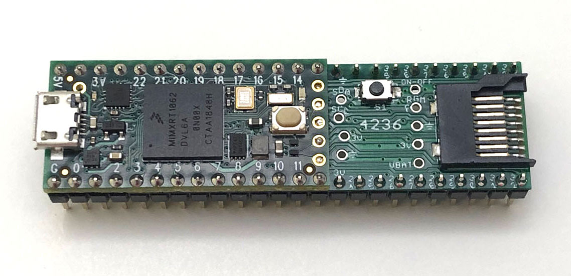
This is the result of soldering with non-clean
flux on rev. A board. |
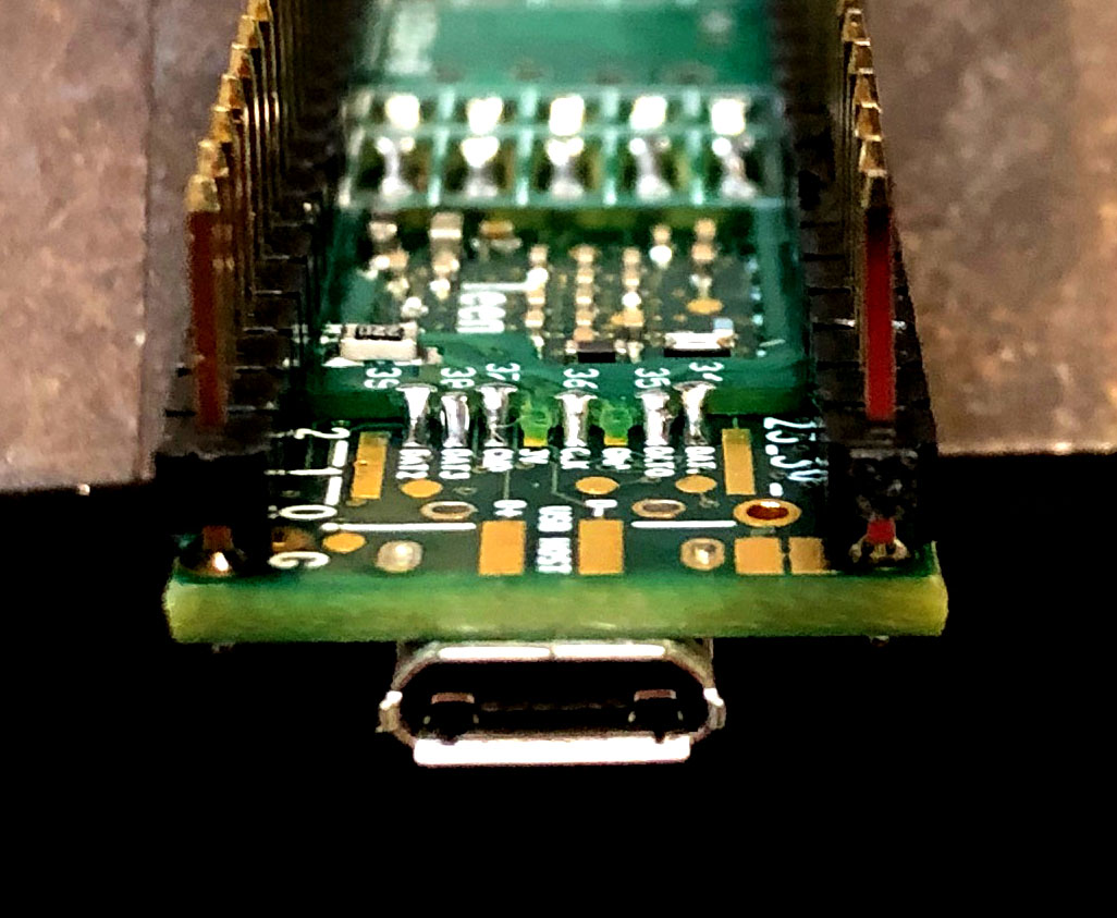 |
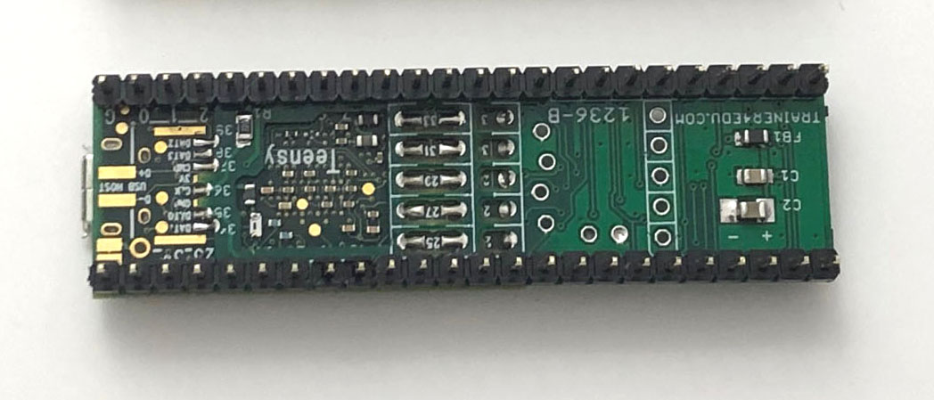
8.
This is the result of soldering with water
soluble flux on rev. B board. The solder joints
look a bit nicer after cleaning with water, but
it doesn't make any better in product
performance.
If you use water soluble flux, you can wash it
with soap, brush it with a tooth brush, brush
and rinse it thoroughly and dry it using a heat
gun or a hair dryer. I used a USB fan to
blow it for all night and test it on the
following day. Just let it sitting to dry
overnight may not be good enough to get rid off
moisture. Either use a heat gun for the
fast result or a small USB fan to blow it over
night. |
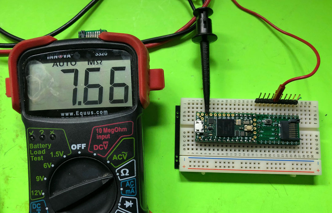 |
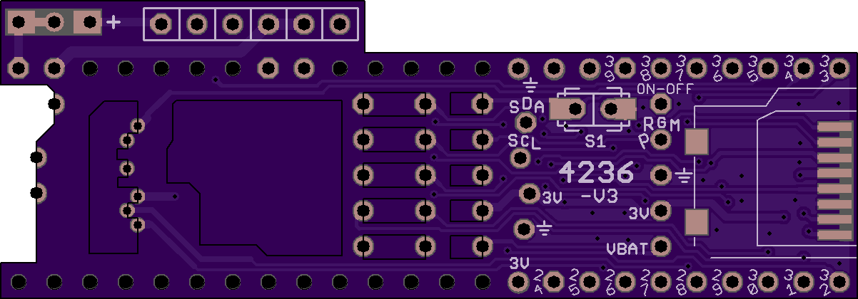
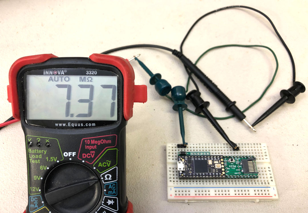
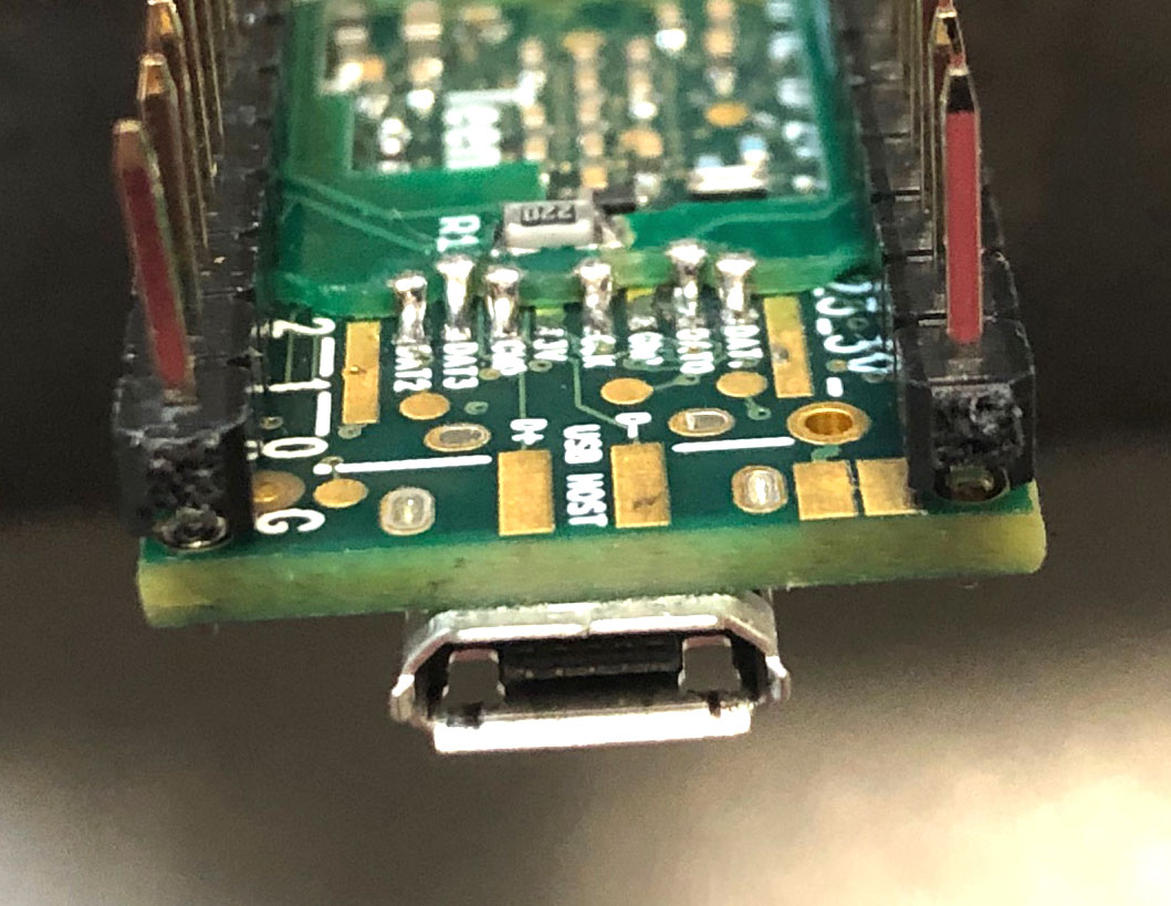
9. Before running a sketch, use a DMM to measure
resistance between each pin of D33-D39 to the
3V. It should be greater than 6 M ohms. Red
probe connects to 3V, black probe connects to a
pin. If
you get a small number, like 10K, your board is
contaminated, it won't work.
You need to see mega ohms.
Also check there should be no shorts in adjacent
pins between D33-D39 which are connected to the
1mm pitch holes. Finally check continuity
between 1mm castellated holes and pin 34- pin39.
This test was done on the rev. A board. (I did
not clean it after soldering it with the flux
just in the solder wire). If you pass this
test, you are all set to use the Teensy 4 with
this breakout board.
|
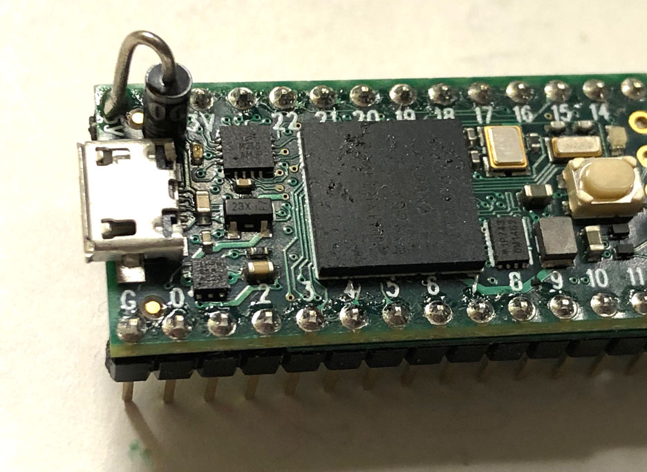 |
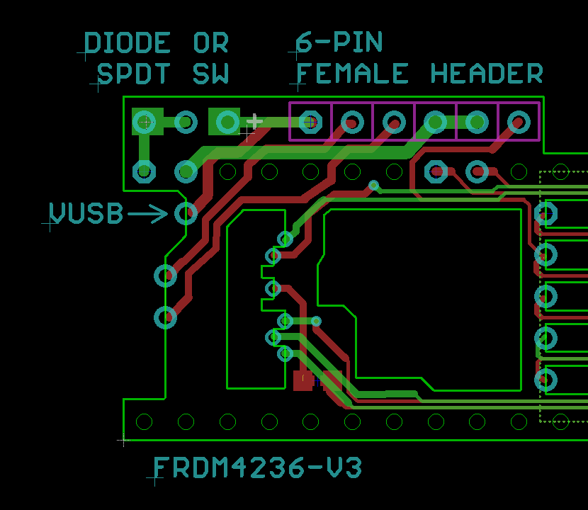
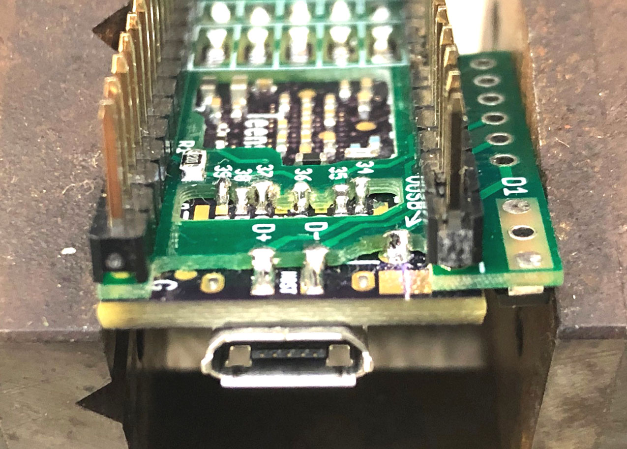
10. If you would like to separate
power sources, VUSB and Vin. The simplest way is
to add a reversing polarity protection diode.
At first, you need to cut the trace between VUSB
and VIN on the solder side.
Then, add a schottky diode.
There is room for adding an 1N5817 schottky
diode on the T4. The pad above the micro
USB jack is VUSB, just solder the anode of
1N5817 to the pad, solder the cathode of 1N5817
to the Vin. After that, you can connect
USB power and external VIN at the same time.
|
 |
 |
|
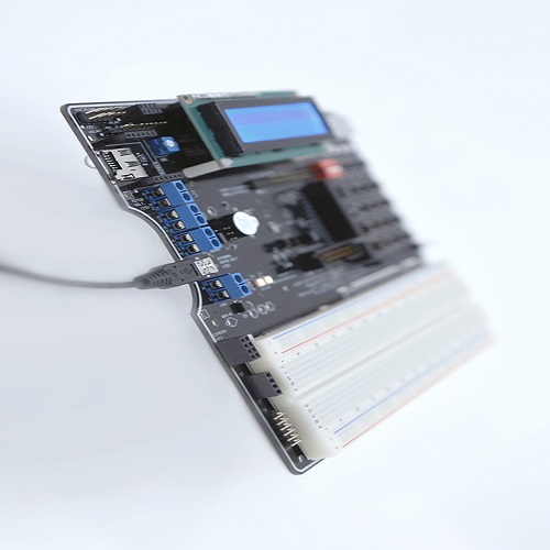
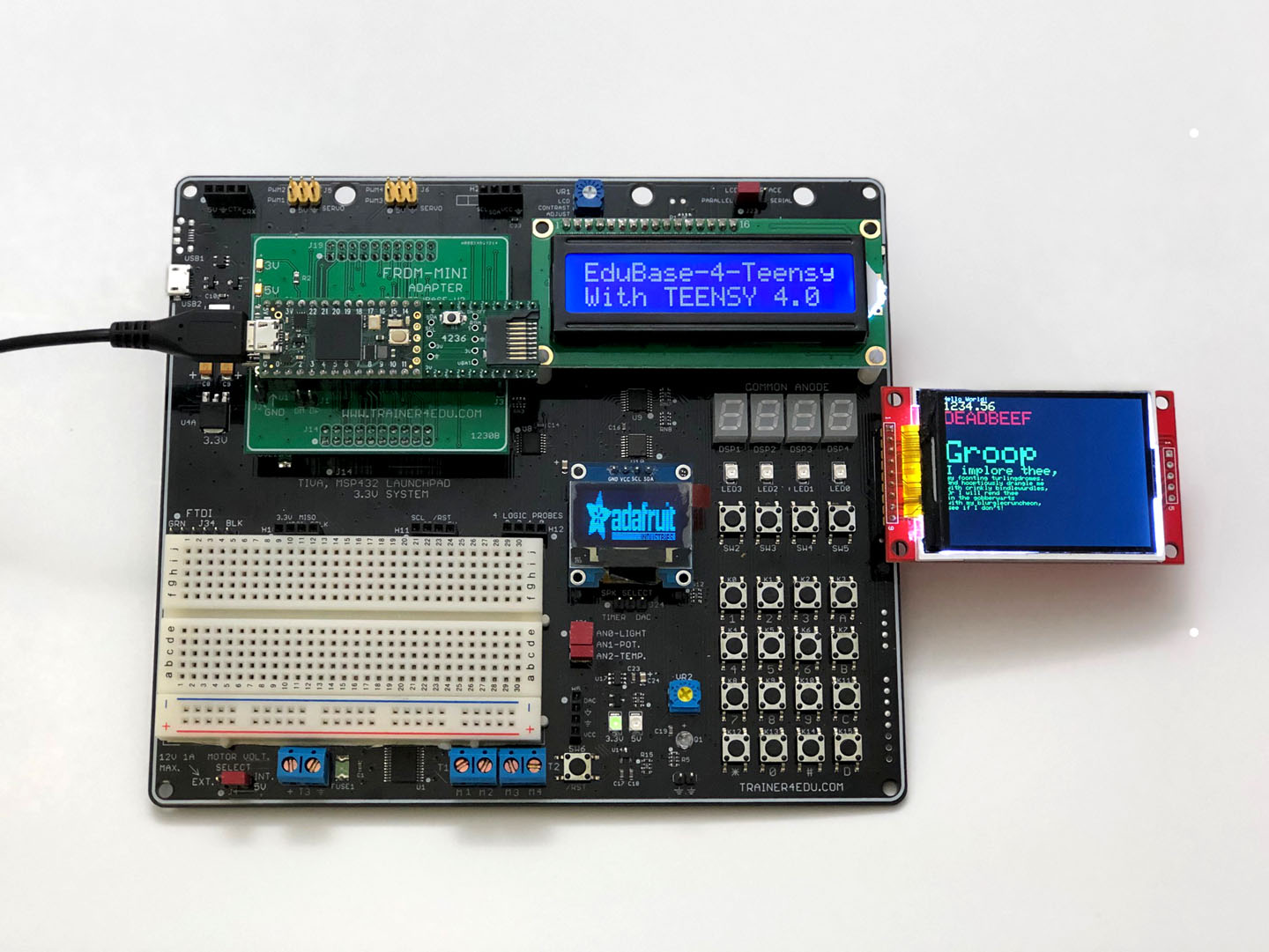
Teensy 4.0 with 3.6 footprint on EduBase-V2 |
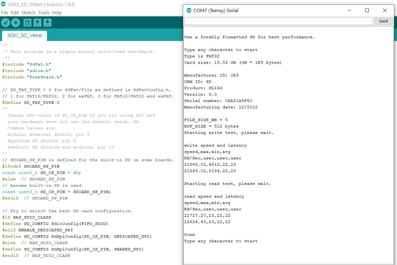
Teensy 4.0 SDIO tested OK with
Bill Greiman's SdFat 2.0.0-beta.3
|
|
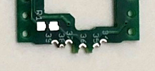
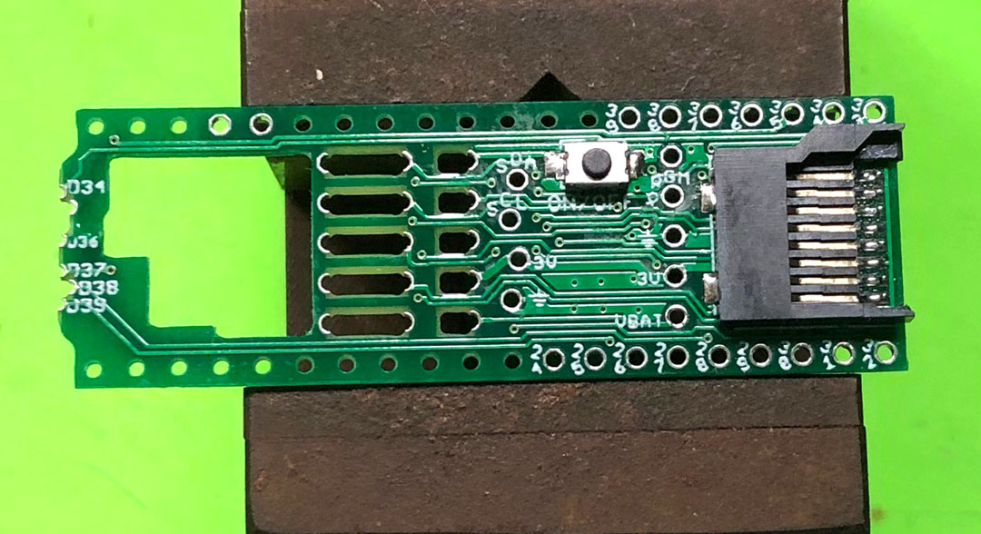
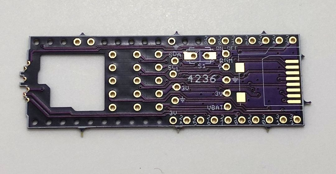
Defective
Oshpark PCB |
|
 |
 |
|
Just received this board from Oshpark a few days
ago. I uploaded Gerber files to Oshpark on
9/23/19, and shared a few days before I stopped
sharing. I felt that it's not a good idea to
share a untested board. Although it was tested
OK with the PCB made by a different
manufacturer. I think that I made a good
decision, otherwise someone could have wasted
money because this time the Oshpark board is
unusable.
|
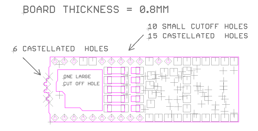
bove is the drilling data file which I specified
15 more castellated holes. The six 1mm-pitch
castellated holes were made OK, but other 15
castellated holes were not made.
If you would like to order this board, you need
to send an email to Oshpark and remind them to
route out all cut off holes.
|
|