 |
|
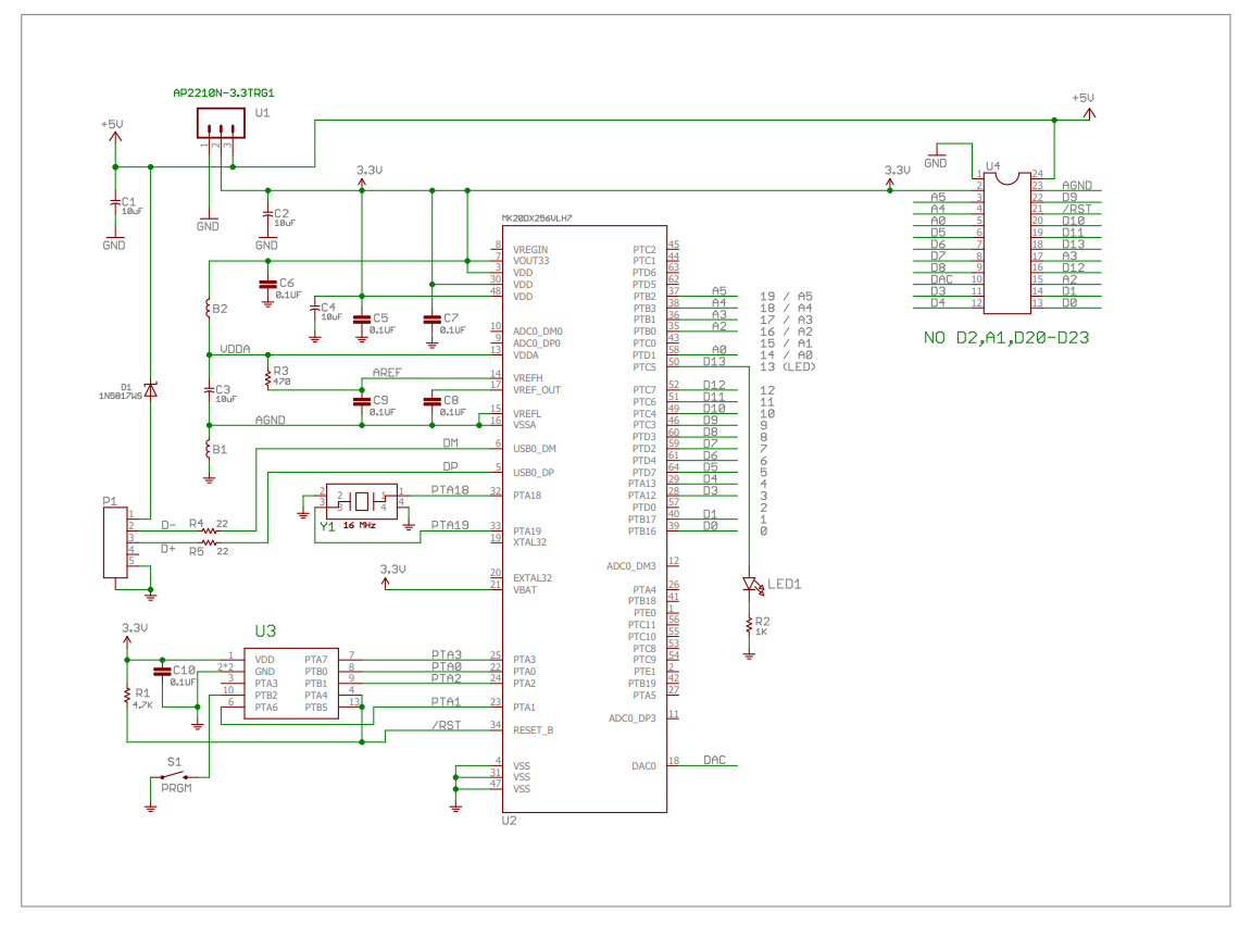
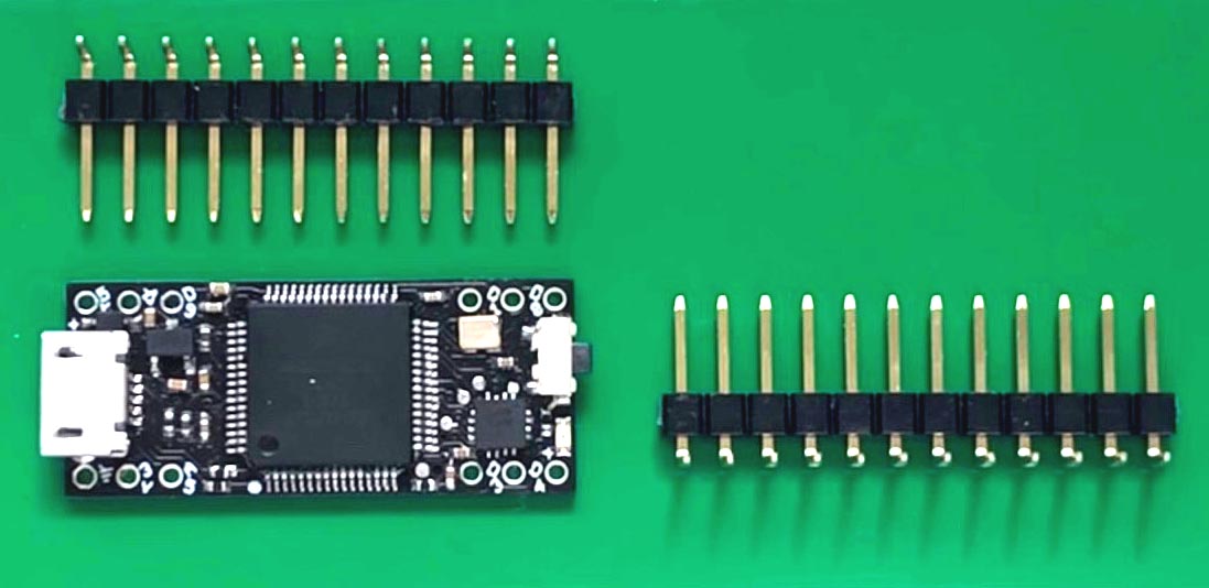
1. Parts needed:
-
One of Mini T3.2 module.-
Two of 12-pin,
right angle, male headers, 0.1" pitch.
-
|
 |
|
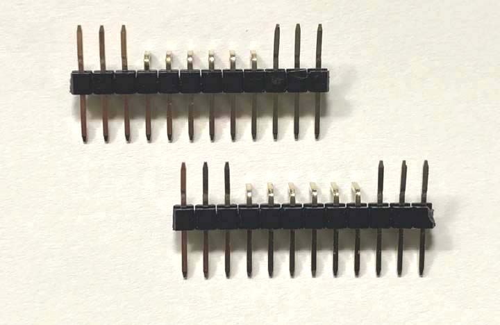
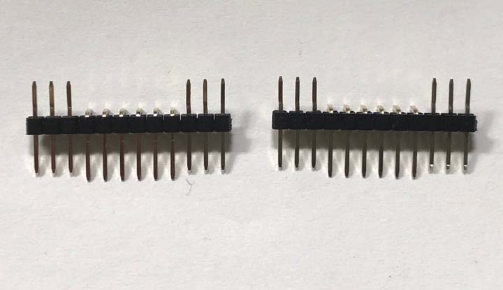
2. Bend the 6 outer pins up. |
 |
|
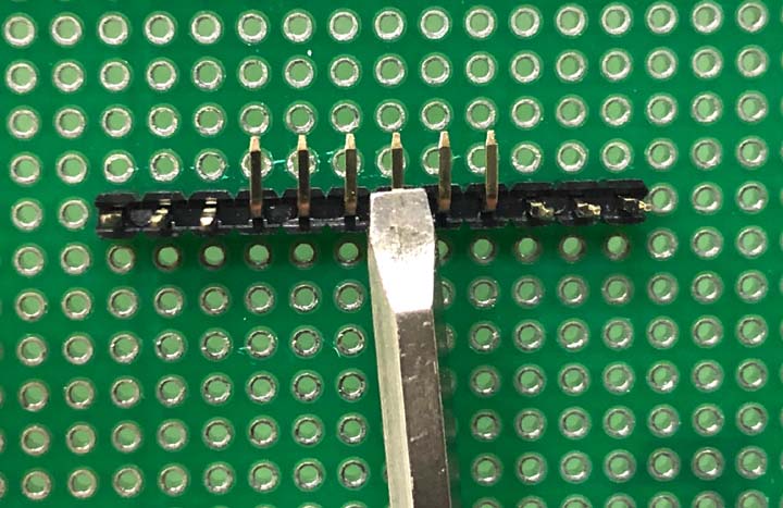
3. Push down the middle 6 pins as much as possible
using a flat screwdriver, one at a time. |
 |
|
4. The middle 6 pins are all pushed down. |
 |
|
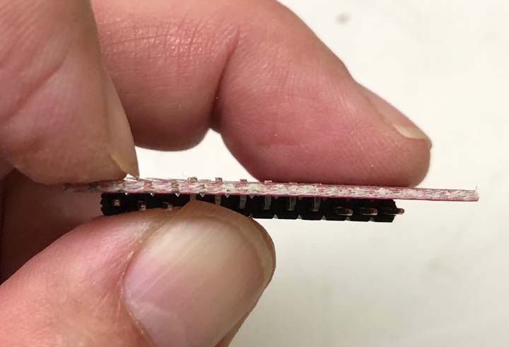
5. If you don't push them down, the final
assembled module will be like this. A
large gap between the module and the headers.
|
 |
|
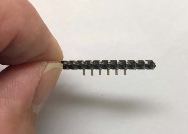
6. Cut down the middle 6 pins to about
half length.
You can use a 1.2mm PCB as a reference
or just estimate how much to cut off.
It does not have to be very accurate.
WARNING:
make sure to wear safety glasses or use a finger
to prevent the cut-ff piece flying. |
 |
|
7.
After cut. |
 |
|
8. The middle 6 pins are shorter. |
 |
|
9. Then put the male headers over the module, you
can see there are a lot of room to add solder. |
 |
|
10. If you don't cut them, the pins are too long
and it's harder to solder them to the pads. |
 |
|
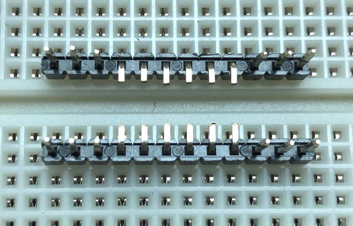
11. Plug two male headers onto breadboard at 0.4"
apart. Make sure it's 0.4" apart, not 0.5"
apart. |
 |
|
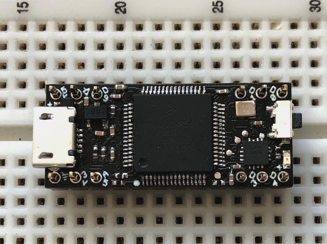
12. Place the Mini T3.2 module over two male
headers.
Start soldering 2 pins, pin1 and
pin13. Solder pins while
pressing down the board. Once those 2
pins are soldered, check to make sure there is
even gap width between the module and the male headers. If
not, you still have a chance to correct it.
See the picture below.
Then solder all other remaining pins.
Be careful when soldering as some pins are close
to components, don't make solder bridges.
|
 |
|
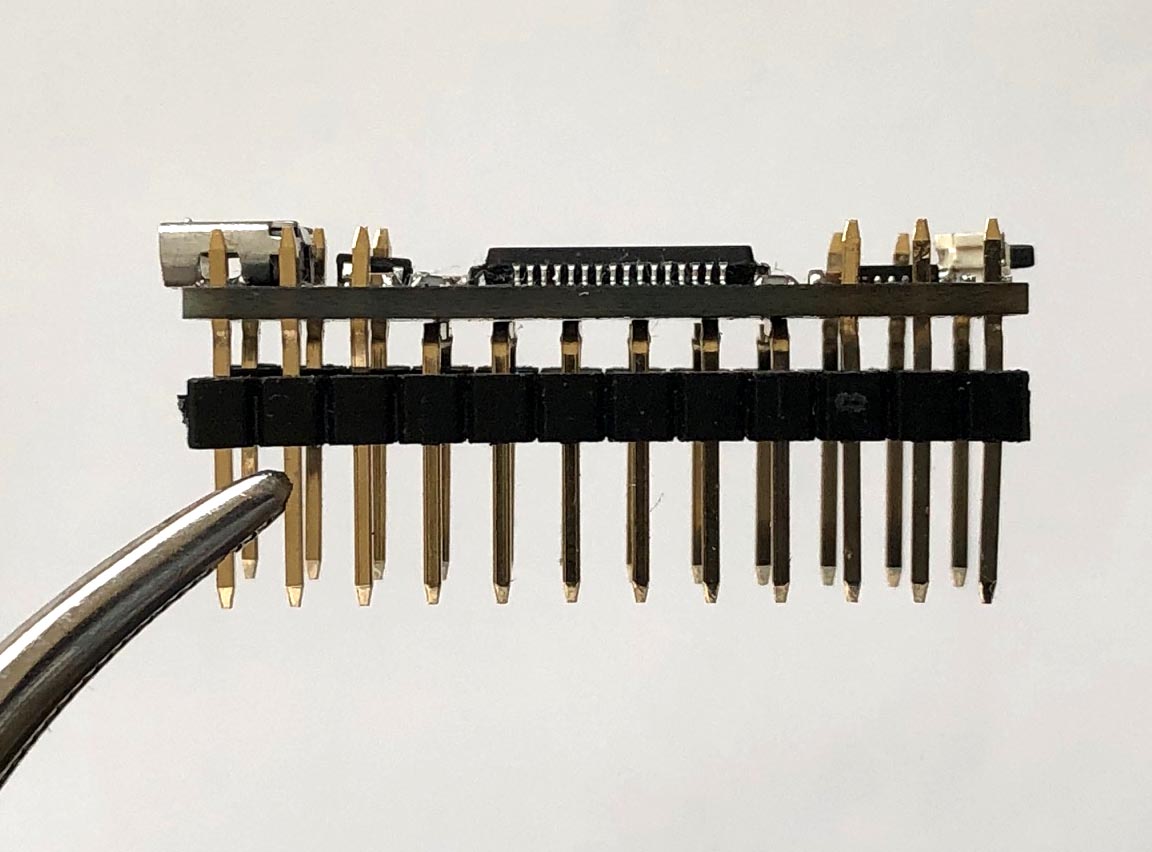
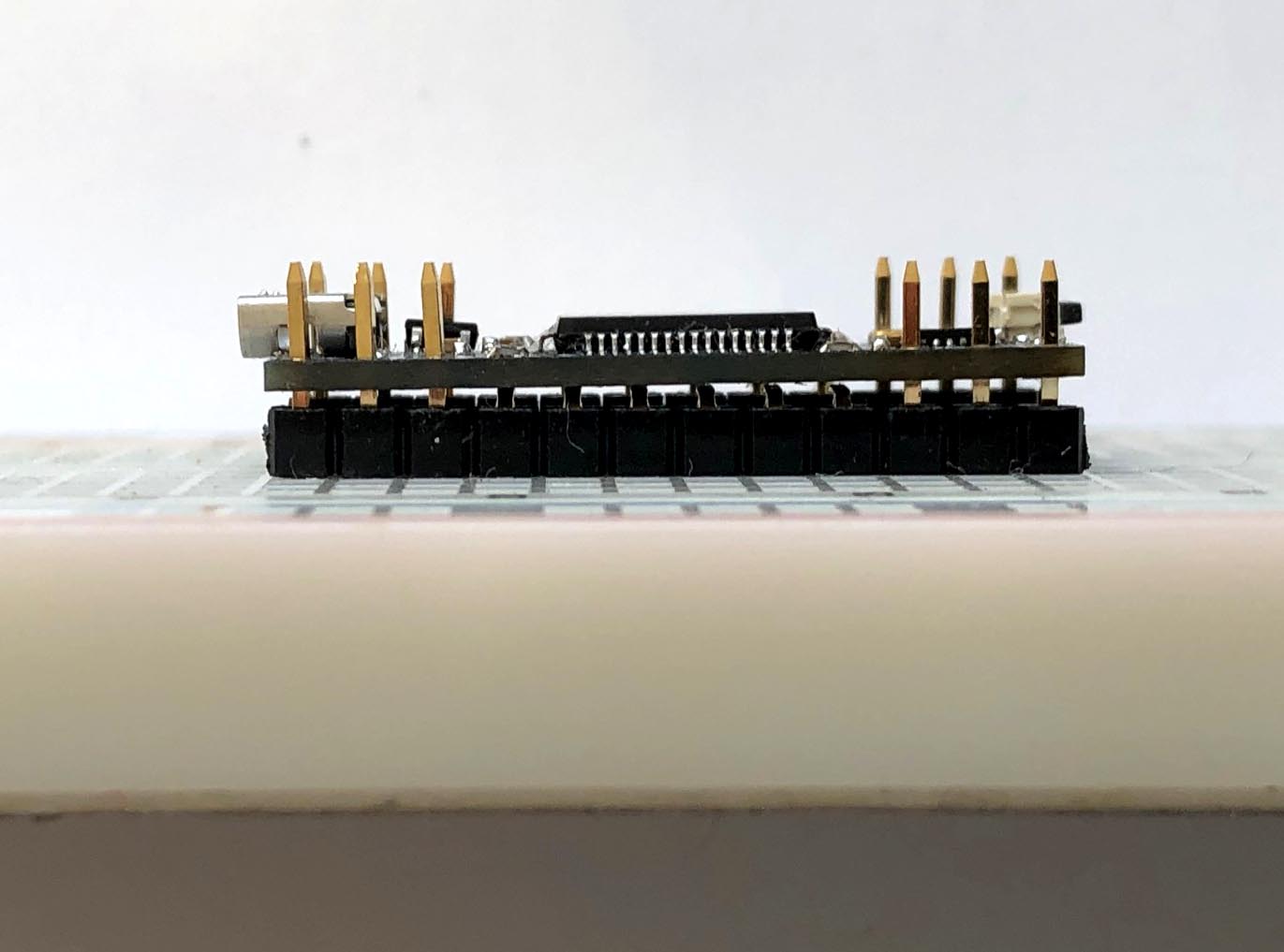
13. The side view of the above picture.
There should be a very small gap
between the module and the male headers. |
 |
|
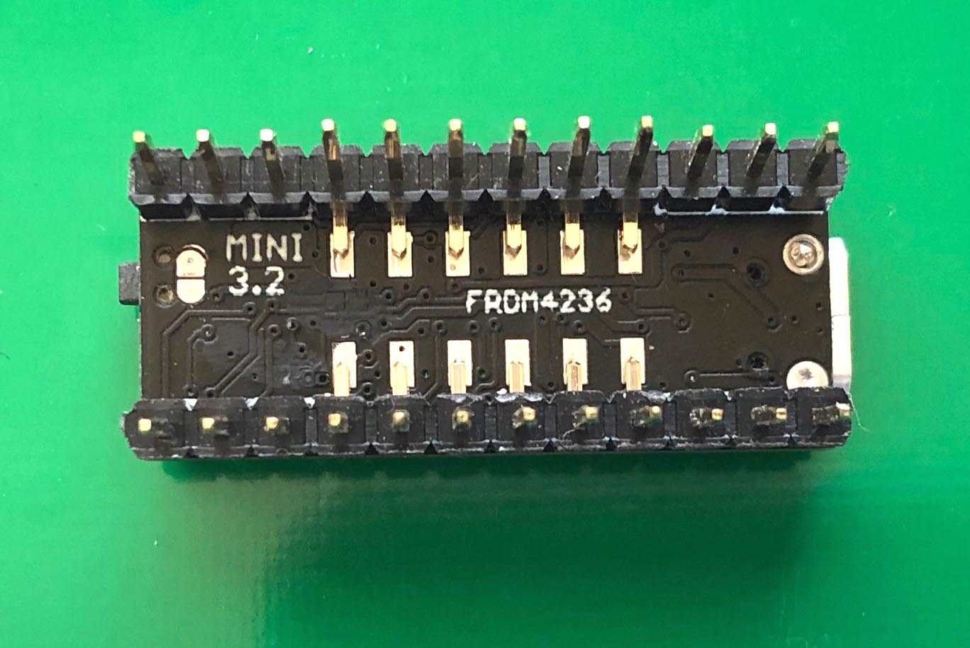
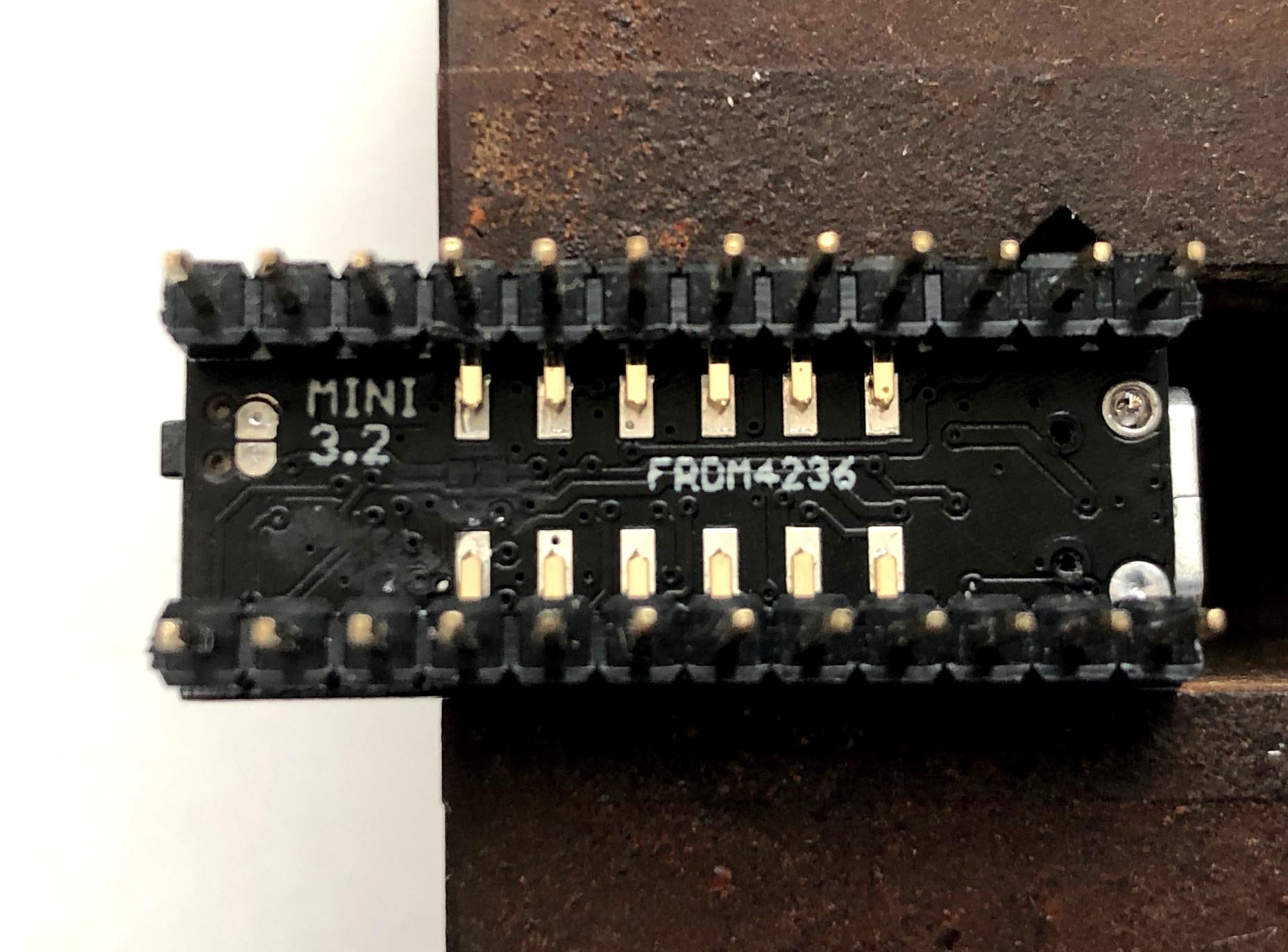
14. After soldering all pins on the top
side turn over the module. |
 |
|
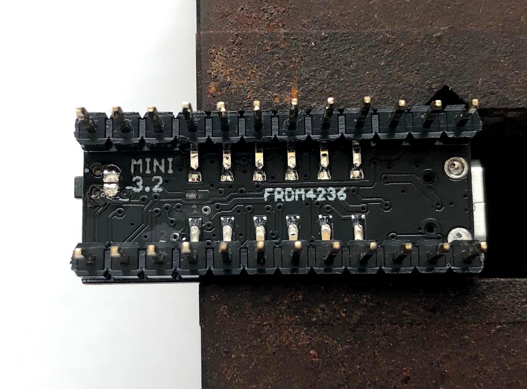
15. Solder all 12 pins on the bottom side. |
 |
|
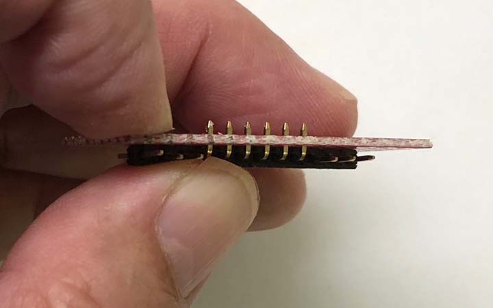
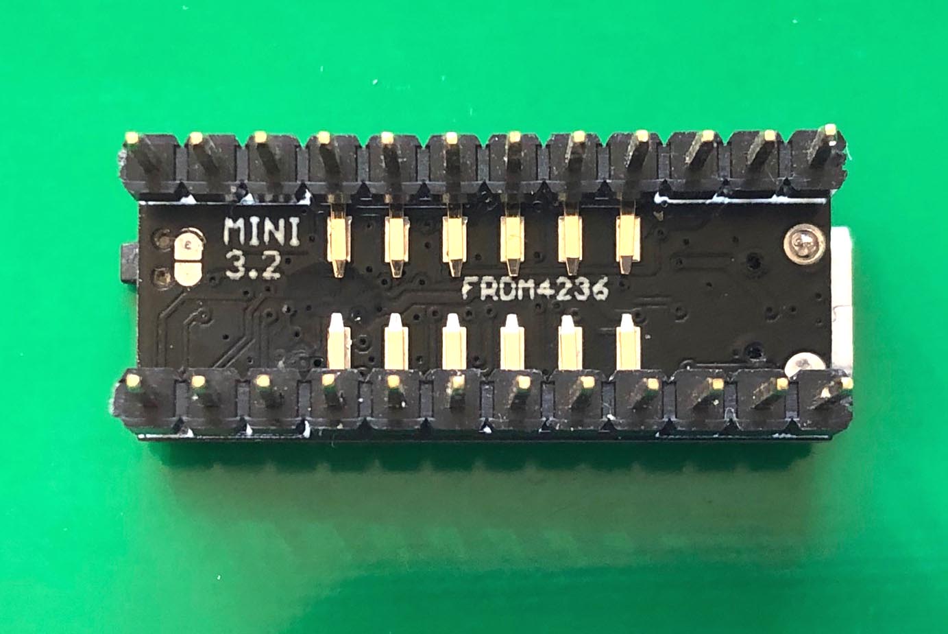
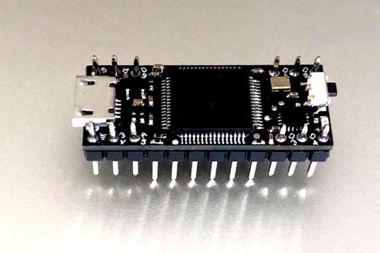
16. This is the final assembled module.
The middle 6 pins on each side are a bit long,
but it still can be plugged into a breadboard.
So it's your choice to trim them or not.
|
 |
|
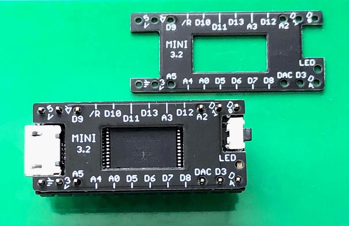
17. The module is small and there is no
room to put all pin names on the top. Without
the pin names it's harder for breadboarding.
You can make a
0.8mm PCB as a label sheet.
Gerber files. |